The format of an operating system’s executable file is in many ways a mirror of the operating system.
–Matt Pietrek
PE or Portable Executable is the Windows executable file format. Studying the PE format helps us understand how windows internals function which in turn makes us better programmers. It is even more important for reverse engineers who want to figure out the intricate details of often obfuscated binaries.
There are several good articles out there on the topic, but most of them trade completeness for readability. MSDN specs are the most complete but hard to understand for newbies. This article focuses more on the import and export directories and is targeted at beginners with little or no knowledge of PE internals.
The figure below shows the basic structure of a PE file. Whenever you execute a file, the windows loader would first load the PE file from disk and map it into memory. The memory map of the PE file is called a module. It is important to note that the loader may not just copy the entire contents from disk to memory. Instead, the loader looks at the various values in the header to find different parts of the PE in the file and then maps parts of it to memory. This has some serious implications on security as explained in the BlackHat presentation by Reversing Labs in 2011.
Note: The field sizes in the format are defined as words and double words. I converted them using 2 byte word size.
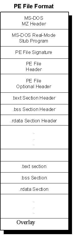
The beginning of every PE file is a MZ header. This is the image DOS header and begins with the magic string “MZ”, ascii representation of the characters MZ ( 0x4D5A ), hence the name. It is important to understand here that the DOS magic signature is 0x5A4D, but being little endian, it is in the order 0x4D5A. (Little endian requires that when writing multiple bytes of data, least significant byte be written in smallest address and higher bytes correspond to higher address).The DOS header has been around before the PE was born. Today it has no use other than alerting the OS about the program’s compatibility. The DOS header is 64 bytes in length. It is followed by a small stub program that typically gives an error message like “This program cannot be run in DOS mode”. DOS programs begin right after the DOS header and hence would run the stub first. This would prompt the above error message and then exit safely. PE loader parses the DOS header and reads the “e_lfanew” field. The PE loader knows that this field contains the address of the PE header and hence jumps to it.
The PE header begins with the PE signature which is 0x00004550. This is actually two null bytes followed by the ascii for “EP”. When in little endian, this becomes “PE<null><null>”. This is followed by the file header and the optional header.
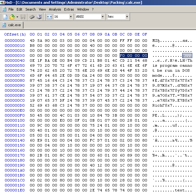
For the purpose of this article, I decided to use the common calculator executable (calc.exe) included in my XP installation.
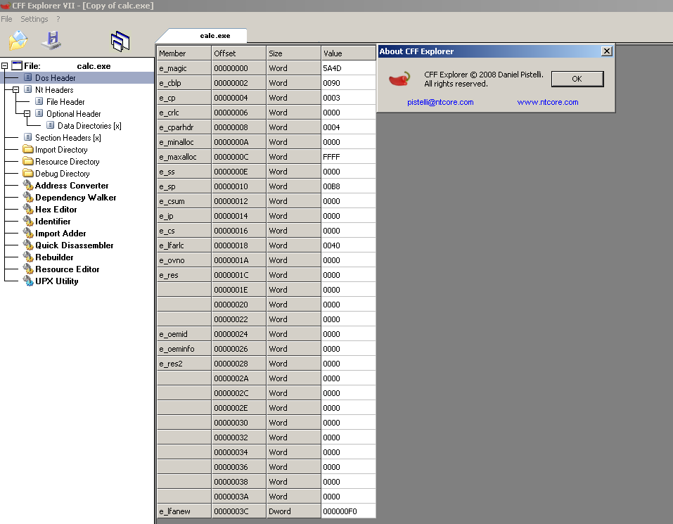
Since it can get difficult to read fields by simply opening the file in a hex editor (though I would definitely recommend doing it atleast once, it’s fun! ), another alternative is to use CFF Explorer by Daniel Pistelli (www.ntcore.com) or similar software.
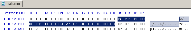
Notice the selected value in Fig 2. These 4 bytes together represent the e_lfanew field. In Fig 3, the value is 000000F0. This is so because CFF Explorer is endianess aware and hence read the field value correctly, while the Hex editor does not do that. Also notice the PE signature at the offset F0 in Fig 2.
Right after the PE Signature is the File Header. The file header is 20 bytes is size and structured as:
2 bytes: Machine

2 bytes: NumberOfSections

4 bytes: TimeDateStamp

4 bytes: PointerToSymbolTable

4 bytes: NumberOfSymbols

2 bytes: SizeOfOptionalHeader

2 bytes: Characteristics
Fields of interest to me here is the Number of Sections and size of Optional Header
For calc.exe, we see the no of sections to be 3 and size of optional header is E0 (=224 bytes). The Optional Header begins right after the File Header. It is structured as:
2 bytes Magic

1 bytes MajorLinkerVersion

1 bytes MinorLinkerVersion

4 bytes SizeOfCode

4 bytes SizeOfInitializedData

4 bytes SizeOfUninitializedData

4 bytes AddressOfEntryPoint

4 bytes BaseOfCode

4 bytes BaseOfData

//28 bytes

//

// NT additional fields.

//

4 bytes ImageBase

4 bytes SectionAlignment

4 bytes FileAlignment

2 bytes MajorOperatingSystemVersion

2 bytes MinorOperatingSystemVersion

2 bytes MajorImageVersion

2 bytes MinorImageVersion

2 bytes MajorSubsystemVersion

2 bytes MinorSubsystemVersion

4 bytes Win32VersionValue

4 bytes SizeOfImage

4 bytes SizeOfHeaders

4 bytes CheckSum

2 bytes Subsystem

2 bytes DllCharacteristics

4 bytes SizeOfStackReserve

4 bytes SizeOfStackCommit

4 bytes SizeOfHeapReserve

4 bytes SizeOfHeapCommit

4 bytes LoaderFlags

4 bytes NumberOfRvaAndSizes

8 bytes IMAGE_DATA_DIRECTORY[16]//8*16 bytes=128
The IMAGE_DATA_DIRECTORY is an 8 byte data structure with two fields: the RVA (Relative Virtual Address) and the size of the corresponding table.
IMAGE_DATA_DIRECTORY

{

4 bytes RVA

4 bytes Size

}
Here is a list of all the data directories in order as they appear in the PE format:
| Entry | Table |
| 0 | Export Directory |
| 1 | Import Directory |
| 2 | Resources Directory |
| 3 | Exception Directory |
| 4 | Security Directory |
| 5 | Base Relocation Table |
| 6 | Debug Directory |
| 7 | Copyright String |
| 8 | GP |
| 9 | Thread Local Storage (TLS) Directory |
| 10 | Load Configuration Directory |
| 11 | Bound Import Directory |
| 12 | Import Address Table |
| 13 | Delay Load Import Descriptor Directory |
| 14 | COM Runtime Descriptor |
Notice that the header reserves space for 16 data directories while there are only 15 listed above (entries 0 through 14). The Entry 15 is null. Right after the Optional Header, lie the section headers. We need to read through them to have the necessary information to convert the RVA in the data directories to physical file offsets. Notice that we already know the number of section from the File Header. The loader will just iterate that many times and read the contents into the SECTION_HEADER structure.
The SECTION_HEADER structure is defined as:
SECTION_HEADER

{

1 byte Name[8] //1*8=8 bytes

union {

4 bytes PhysicalAddress //for obj files only

4 bytes VirtualSize // actual size of section for exe files

}Misc

4 bytes VirtualAddress

4 bytes SizeOfRawData //section size rounded up to file alignment

4 bytes PointerToRawData

4 bytes PointerToRelocations

4 bytes PointerToLinenumbers

2 bytes NumberOfRelocations

2 bytes NumberOfLinenumbers

4 bytes Characteristics

}//40 bytes
Since I am most interested in how imports work in PE32, The first entry to look at is entry 1: Imports Directory. The header suggests that the RVA for Imports Directory is 0x00012B80 and the size is 0x0000008C. The RVA can easily be converted to the physical offset in the file. We look up the section headers to find the section containing the above RVA.
The .text section begins at VirtualAddress 0x1000 and has VirtualSize of 0x126B0. The SectionAlignment (See Optional Header) is 0x1000, this means that when the loader maps sections into memory regions of size that is multiple of 0x1000. This is so because the loader allocated memory in pages which are of 4096 bytes (=0x1000 bytes) each. In the file, actual bytes of the section are mapped in regions of size that is a multiple of the FileAlignment. Here, the FileAlignment was 0x200(=512 bytes) which is the size of one sector on a disk. Typically, the section would be null padded to fill up the extra space.
Hence the space occupied by the .text section which is actually 0x126B0 in size,
- on the disk(in file)=0x128B0
- on memory=0x13000
Clearly, the Imports Directory, which begins at virtual address 0x12B80, is located in the .text section which ranges from 0x1000 through 0x13FFF in the memory. Hence, to locate the directory in the file, we locate the .text section in the file and look at the offset of the directory in the section. The section is located at 0x400 (PointertoRawData field in the section header). The offset of Import Directory within the section is 0x12B80-0x1000=0x11B80. Hence the physical offset(file offset) of the Import Directory is 0x400+0x11B80=0x11F80. Looking up this address in the hex editor, we should be able to find the Import Descriptors that the directory entry points to.
The IMPORT_DESCRIPTOR structure is as defined below:
IMPORT_DESCRIPTOR

{

union {

4 bytes Characteristics

4 bytes OriginalFirstThunk

}

4 bytes TimeDateStamp // 0 if not bound,

// -1 if bound, and real date\time stamp

// in IMAGE_DIRECTORY_ENTRY_BOUND_IMPORT (new BIND)

// else date/time stamp of DLL bound to (Old BIND)
4 bytes ForwarderChain // -1 if no forwarders
4 bytes Name //Pointer to string with name of DLL file.
4 bytes FirstThunk // RVA to IAT (if bound this IAT has actual addresses)
}
We can calculate the size of an Import descriptor from above to be equal to 20 bytes. The number of descriptors thus is given by (directory size / 20 bytes). Here, it is 7. Also, since the last descriptor is always null, it is actually 6. The image below lists all of the 6 import descriptors as seen in the CFF Explorer.
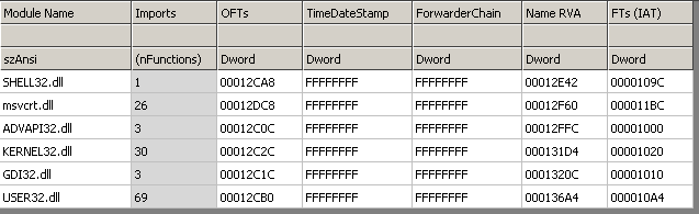
For the sake of brevity and avoiding redundancy, I will pick just one descriptor and continue with it for the rest of the article. Let’s pick Advapi32.dll descriptor.
The descriptor has values as follows:
IMPORT_DESCRIPTOR

{

union {

4 bytes Characteristics //not used as characteristics anymore. Deprecated use case

4 bytes OriginalFirstThunk //=0x12C0C

}

4 bytes TimeDateStamp //=0xFFFFFFFF
4 bytes ForwarderChain //=0xFFFFFFFF
4 bytes Name //0x12FFC
4 bytes FirstThunk //0x1000
}
The Original First Thunk field points to a null terminated array of pointers. Each pointer then points to ab IMAGE_IMPORT_BY_NAME structure (explained later). The virtual address 0x12C0C is equivalent to 0x12C0C-0x1000+0x400=0x1200C in file offset. The null terminated array of 4 byte pointers, at that address, is highlighted in the image below.
Since there are three pointers, before the null terminating pointer, we now know that only 3 functions are being imported using this descriptor. To look at the actual IMAGE_IMPORT_BY_NAME structure, we need to again convert these RVA to physical offsets. Lets take the first RVA. It points to physical offset 0x123EC.
This is the location to the IMAGE_IMPORT_BY_NAME structure. The structure is defined as:
IMAGE_IMPORT_BY_NAME

{

2 bytes Hint

1 byte Name[?] //null terminated string

}
At the location 0x123EC, we read the IMAGE_IMPORT_BY_NAME structure as:
Hint=0x1E1

Name=RegOpenKeyExA
Similarly reading the other two IMAGE_IMPORT_BY_NAME structures:
Hint=0x1EB

Name=RegQueryValueExA
Hint=0x1C8
Name=RegCloseKey
The hint field is the best guess for the ordinal of the function in the DLL. This is not required to be correct and is only used as a starting point by the loader, for it’s search of the function in the dll.
The timestamp and forwarder chain fields both equal -1.
The name field is RVA 0x12FFC. This is physical offset 0x123FC which points to the beginning of the null terminated string ADVAPI32.dll
Next, is the first thunk field containing RVA 0x1000. Again, this points to a null terminated array of IMAGE_THUNK_DATA structure. This structure is defined as:
IMAGE_THUNK_DATA

{

union {

4 bytes ForwarderString; //Pointer to null terminated string

4 bytes Function; //Pointer to a function

4 bytes Ordinal; //Ordinal

4 bytes AddressOfData; //Pointer to IMAGE_IMPORT_BY_NAME structure

}

}
Almost always, the union is interpreted as pointer to IMAGE_IMPORT_BY_NAME structure. Initially this contains the addresses. I am still to understand how the other interpretations work (if at all they work now!).
This second array of IMAGE_IMPORT_BY_NAME structure is overwritten by the PE loader with the addresses of the function that the IMAGE_IMPORT_BY_NAME structure refers to. This is why this First_Thunk array, is also called as Import Address Table because it contains the actual addresses of the functions. The first array of IMAGE_IMPORT_BY_NAME structure, the Original_thunk array, is never changed. Since it contains the hint to ordinal and the name of the imported function, it is also called as Hint-Name Table.
When you call a function imported from a DLL, the linker converts the call statement to a
JMP DWORD PTR [xx] statement where [xx] is the address of the corresponding IAT entry. That is why all jumps work correctly once the loader has converted the First_Thunk to IAT.
Hope this helps! In the next article, I will talk about bound and delay imports.
To report suggestions,corrections/bugs or any other feedback, mail to vxn4849@louisiana.edu
Pingback: lance
Pingback: Gregory Smith
Pingback: займ на карту